If you’ve ever worked with high-temperature materials processing—whether it’s ceramics, metallurgy, or even advanced heat treatment for aerospace parts—you know a resistance furnace is only as good as its ability to deliver consistent, accurate temperatures. Over the 12 years I’ve been selling, installing, and supporting resistance furnaces, I’ve seen too many customers skip calibration steps, only to end up with ruined batches, wasted time, and lost money. Calibration isn’t just a factory chore; it’s the difference between a furnace that meets industry standards and one that becomes a liability. Today, I’m breaking down exactly how to calibrate a resistance furnace, straight from the perspective of someone who’s worked with these units every single day. Resistance Furnace
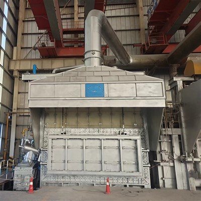
First, let’s get one thing straight: calibration isn’t a one-and-done task. I’ve seen customers run a calibration once when they unbox a new furnace, then never touch it again for five years. That’s a mistake. Resistance furnaces experience wear and tear: heating elements degrade, insulation settles, thermocouples drift, and even small changes to power supply voltage throw off temperature readings. For most industrial operations, I recommend calibrating your furnace quarterly, or after any major maintenance (like replacing heating elements), and always before a critical production run. If you’re working with highly regulated industries—pharmaceuticals, aerospace, or automotive heat treatment—you’ll need to follow ISO 9001 or AMS 2750 guidelines, which require more frequent calibration, often monthly.
Before you even pick up a thermocouple or a temperature data logger, you need to gather the right tools. I’ve talked to customers who try to use a cheap digital thermometer from a hardware store for calibration, and it never works. Here’s what you actually need: a calibrated reference thermocouple (type K is standard for most medium-temperature furnaces, but type S is better for high-temperature work above 1200°C), a data logger that can record readings at 10-second intervals for at least 4 hours, a high-temperature insulating block to hold the reference thermocouple safely inside the furnace’s hot zone, and a clean, empty furnace chamber (no parts, no crucibles, no debris blocking heat flow). Also, make sure your power supply is stable before you start—if the voltage fluctuates by more than 5%, your readings will be off, so check that first with a multimeter.
The first step in calibration is mapping the hot zone. This is non-negotiable, especially for larger furnaces. The hot zone isn’t just the middle of the chamber; depending on how heating elements are arranged, there can be hot spots 20-30°C higher in one corner, and cold spots 15°C lower in another. I once had a customer who was ruining a batch of custom ceramic components because they were loading parts in the cold corner—they thought the furnace’s display was accurate, but it was only measuring the temperature near the controller, not where the parts actually were. To map the hot zone, place your reference thermocouple at 5 different points: front-left, front-right, back-left, back-right, and the center of the chamber. Set the furnace to a standard test temperature—for most general calibration, 1000°C works, but you can test at multiple temperatures (like 500°C, 800°C, and 1200°C) to confirm consistency. Let the furnace stabilize at each temperature for 30 minutes, then record readings from your reference thermocouple and compare them to the furnace’s display. If the difference between any point and the display is more than 5°C, your hot zone is uneven, and you might need to adjust heating element alignment or fix insulation gaps—something a good furnace service tech can help with.
Next, you’ll calibrate the temperature sensors, specifically the thermocouple connected to the furnace’s controller. Thermocouples drift over time, usually by 1-3°C per year, but if they’re exposed to corrosive atmospheres or high temperatures above their rated limit, drift can be much faster. For example, a type K thermocouple is only rated up to 1260°C—if you run it at 1300°C regularly, the metal sheath will erode, and readings will start to skew. To calibrate the thermocouple, take your reference thermocouple and place it in the same location as the furnace’s controller thermocouple—usually, that’s a hole in the furnace wall, 1-2 inches into the hot zone. Set the furnace to a test temperature, let it stabilize for 45 minutes, then note the reading from the controller and the reading from your reference. If the controller reads 1000°C but your reference reads 996°C, that’s a 4°C difference, which is within acceptable limits for most applications. If the difference is more than 5°C, you’ll need to adjust the controller’s calibration offset. Most modern resistance furnaces let you do this through a simple menu setting—just enter the offset value (in this case, -4°C) to make the controller’s display match the reference.
Wait a second—what about cold junction compensation? That’s a common mistake I see. Thermocouples measure the difference in temperature between the hot end (inside the furnace) and the cold end (where the wire connects to the controller). If the cold junction’s temperature isn’t accounted for, your readings will be wrong. Most controllers have automatic cold junction compensation, but it’s good to verify it. You can do this by placing the cold end of your reference thermocouple in an ice bath (0°C) and checking that the controller’s reading matches the reference at room temperature. If they don’t, manual adjustment might be needed, though this is rare with newer controllers.
Once you’ve calibrated at the 1000°C mark, you should also test the low end of your furnace’s operating range, usually 200°C to 400°C, and the high end. For high-temperature furnaces rated up to 1600°C, test at 1500°C too. Why? Because heating element resistance changes with temperature. A heating element that works perfectly at 500°C might drift slightly at 1500°C, so your calibration needs to cover all the temperatures you actually use. I recommend testing at 2-3 of your furnace’s most common operating temperatures—if you mostly run at 800°C for ceramic sintering, test that regularly, not just the midpoint.
After you’re done with the in-furnace tests, you need to perform a drift check, also called a long-term stability test. Let the furnace run at a constant temperature for 8 hours, recording readings every 10 minutes. If the temperature varies by more than ±5°C over that time, that’s a sign of a problem—maybe a loose connection in the heating elements, or insulation that’s starting to fail. I had a customer a few years ago who thought his furnace was ruined, but it turned out a single heating element wire had corroded, causing temperature fluctuations; replacing it fixed the drift in an hour.
Now, let’s talk about common mistakes to avoid. First, don’t calibrate right after opening the furnace door. If you open the door every 10 minutes to load parts, the temperature will drop, and your calibration will be off. Always run calibration with the door closed, and let it stabilize for at least 30 minutes before recording readings. Second, don’t use the same thermocouple for test runs and calibration. Your reference thermocouple should be a calibrated, NIST-traceable unit—this means its accuracy is certified by a national standards body, so you can trust the readings. If your reference thermocouple is itself out of calibration, all your work is useless. Third, don’t forget to log everything. Keep a calibration journal with dates, temperatures tested, offset values, and any issues you found. For regulated industries, this log is required for audits, and it also helps you spot trends—if your calibration offset is getting bigger every quarter, that means your thermocouple is wearing out, and you should replace it before it fails.
I also want to share a quick tip for anyone who owns a smaller tabletop resistance furnace, which is super popular for research labs and small batch production. These units often have smaller hot zones and simpler controllers, so calibration is even more critical. A lot of lab managers I work with skip mapping the hot zone for their tabletop furnace, then wonder why their sintered samples come out inconsistent. For these units, testing at 600°C (a common lab temperature) is usually enough, but still take the time to check multiple spots inside the chamber.

Once you’ve completed calibration, you’re not done with maintenance. Calibration goes hand-in-hand with furnace upkeep. Every time you replace a heating element or insulate, you’ll need to re-calibrate. Also, keep your furnace clean—debris from previous runs can insulate parts of the chamber, causing hot spots, and corrosive fumes can damage thermocouples. Wipe down the chamber after each run, and inspect thermocouple sheaths every 6 months for cracks or corrosion.
Tempering Furnace At the end of the day, calibrating a resistance furnace isn’t about following a list of steps—it’s about ensuring your process is reliable. Whether you’re producing high-performance metal parts, custom ceramics, or testing new materials, accurate temperature control is the foundation of consistent quality. If you’re not sure about any part of this process, or you need a calibrated reference tool, a controller adjustment, or even a new resistance furnace that’s built for easy calibration, don’t hesitate to reach out. I’ve worked with hundreds of customers to get their furnaces calibrated correctly, and I’m here to help you too. Whether you’re a small lab or a large manufacturing plant, we can walk through your specific needs, answer your questions, and find the right solution for your temperature processing.
References
- ASM International. (2017). Heat Treater’s Guide: Practices and Procedures for Irons and Steels. ASM International.
- International Organization for Standardization. (2019). ISO 9001:2015, Quality management systems — Requirements. ISO.
- American Society for Testing and Materials. (2020). ASTM E1444, Standard Practice for Temperature Measurement in Industrial Furnaces. ASTM.
- Campbell, F. C. (2012). Manufacturing Technology for Aerospace Structural Materials. Elsevier.
- Reddy, R. G. (2016). High Temperature Materials and Processes. CRC Press.
Danyang Dingfeng Industrial Furnace Co., Ltd.
Danyang Dingfeng Industrial Furnace Co., Ltd. is one of the most experienced resistance furnace manufacturers and suppliers in China, also supports customized service with low price. Please feel free to wholesale high quality resistance furnace made in China here from our factory. For pricelist, contact us now.
Address: Lizhuang Economic Development Zone, Danyang City
E-mail: saleszk@dffurnace.com
WebSite: https://www.dffurnace.com/
